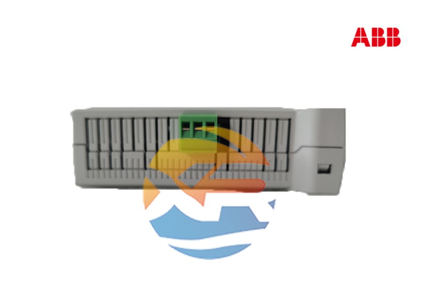
Specifying the correct components is the first step; proper installation is what ensures a control system's reliability. The ABB 520PSD01 power distribution module is a critical link in the power chain. This guide provides a practical, step-by-step overview for panel designers and technicians, covering the key considerations for selecting, installing, and troubleshooting this module within an ABB PLC system, such as the AC 500 series.

Pre-Installation: Selection and Verification
Warning: All electrical work must be performed by qualified personnel following local safety regulations. Disconnect all power before installation.
1. Verify Compatibility
The 520PSD01 is designed for specific PLC racks. Before procurement, confirm its compatibility with your target system (e.g., the ABB AC 500 PM5xx rack). Using an incompatible module can damage the module and the other components in the rack.
2. Check Power Requirements
- Input Voltage: Determine the input voltage rating of your specific 520PSD01 module (e.g., 24V DC or 120/230V AC). This must match the voltage provided by your main panel power supply or the main circuit.
- Power Capacity: Verify the module's total power output capacity (in watts). Ensure that the combined power consumption of all modules in the rack (CPU, I/O, etc.) does not exceed this rating. Overloading the module will cause it to shut down or be damaged.
Step 1: Physical Installation
- Rack Mounting: Ensure the PLC rack is securely mounted in the control panel.
- Module Insertion: Identify the correct slot for the power supply module. This is usually the left-most slot (slot 1) in the rack. Carefully slide the 520PSD01 module into the slot, ensuring it is aligned with the guides.
- Secure the Module: Push the module firmly into place until it engages with the backplane connector. Tighten the mounting screws or latch the module lever to secure it.
Step 2: Electrical Wiring
1. Input Power Wiring
- Source Connection: The input power will come from either a dedicated 24V DC power supply or directly from an AC main via a disconnect switch and fuse.
- Wiring to Terminals: Connect the line (L) and neutral (N) for AC versions, or positive (+) and negative (-) for DC versions, to the designated input terminals on the 520PSD01. Refer to the module's labeling and the hardware manual.
- Grounding: Connect the protective earth (PE) ground wire to the designated grounding terminal on the module. This is essential for safety and noise immunity.
2. Output Power Distribution
- Backplane Power: Once the input power is connected and the module is powered, it will automatically distribute power to the entire rack via the backplane. No additional wiring is needed for this function.
- Auxiliary Outputs (if available): Some power distribution modules have auxiliary output terminals to power external devices (e.g., a small HMI or sensors). If your 520PSD01 has these, wire them as needed, ensuring you do not exceed the current rating for these terminals.
Step 3: Commissioning and Testing
- Visual Inspection: Double-check all connections for tightness and correct polarity.
- Apply Power: Energize the main power supply to the panel.
- Check Status LEDs: Observe the LED indicator on the 520PSD01. A solid green light typically indicates that input power is present and the module is operating correctly. A red or off light may indicate a fault or no power.
- Check Downstream Modules: Verify that the CPU and other modules in the rack power up correctly. Their status LEDs should also indicate normal operation.
- Measure Voltage: Use a multimeter to measure the voltage on the backplane or at the terminals of an I/O module to confirm it is within the specified range (e.g., 24V DC ±5%).
Common Issues and Troubleshooting
- Module Not Powering Up:
- Check the input voltage at the module's terminals.
- Verify the main disconnect switch or circuit breaker is closed.
- Check the fuse on the main power supply (if applicable).
- Downstream Modules Not Powering Up:
- Ensure the 520PSD01 is firmly seated in the backplane.
- Verify the total power consumption of all modules does not exceed the 520PSD01's capacity.
- The module's internal protection may have tripped due to an overload. Cycle power to reset it, but first investigate the cause of the overload.
- Intermittent Resets:
- This can be caused by electrical noise. Verify that all grounding connections are secure.
- Ensure the power and signal cables are properly separated in the panel.
Conclusion
Integrating the ABB 520PSD01 is a straightforward but critical process. By carefully selecting the right module, following correct wiring practices, and performing thorough commissioning checks, you can establish a stable and reliable power foundation for your entire control system. This attention to detail pays dividends in the form of reduced downtime and increased operational reliability. Always consult the official ABB 520PSD01 Hardware Manual for the most precise and detailed instructions.
