Specifying a component is the first step; its correct installation and integration are what lead to a reliable control system. For system integrators and panel builders working with the ABB AC 500 PLC, integrating a digital input module like the ABB P4LR 1KHL015107R0001 is a routine but critical task. This guide provides a practical, step-by-step overview of the selection, wiring, and commissioning process for this module.
Pre-Installation: Selection and Verification
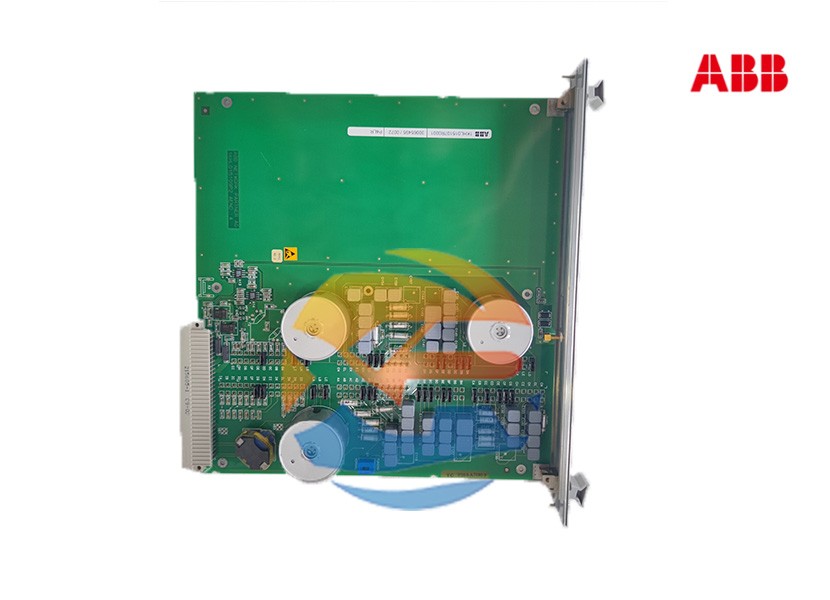
1. Confirm the Module Type
The 1KHL015107R0001 is a 24V DC Digital Input (DI) module. Before procurement, confirm that this is the correct type for your sensors. Are your field devices (e.g., sensors, switches) providing a 24V DC signal? Using an AC input module for DC signals (or vice versa) will damage the module.
2. Calculate I/O Requirements
This module has 8 inputs. Count the number of digital sensors and switches in your system. If you need more than 8 points, you will need to plan for additional DI modules and ensure there are enough slots available in your PLC rack.
3. Verify System Compatibility
The P4LR module is designed for the AC 500 PLC system. Ensure you have a compatible baseplate/rack (e.g., from the PM5xx series). The module will slot directly into the rack and communicate via the backplane.
Step 1: Hardware Installation
Warning: All installation must be performed by a qualified person with all power disconnected.
- Power Down: Completely disconnect power from the PLC rack and the 24V DC supply that will power the field devices.
- Module Insertion: Locate an available slot in the AC 500 baseplate. Carefully insert the P4LR module into the slot, ensuring it is aligned correctly. Press firmly until it clicks into place on the top and bottom. Secure it with the mounting screws if provided.
- Field Wiring: Connect the field devices to the module's terminal connectors.
Step 2: Wiring the Field Devices
This is a crucial step for noise immunity and reliability.
Wiring a Sourcing (PNP) Sensor
A 3-wire sensor typically has Brown (+24V), Blue (0V), and Black (Output) wires.
- Connect the sensor's Brown wire to the +24V DC power supply.
- Connect the sensor's Blue wire to the 0V (Common) of the same power supply.
- Connect the sensor's Black (output) wire to the desired input terminal (e.g., I0.0) on the P4LR module.
- Connect the L- terminal of the module to the 0V (Common) of the power supply. This provides the common reference point for all inputs.
Best Practices for Wiring
- Use Shielded Cable: For analog signals or in electrically noisy environments, use shielded cables. Connect the shield to the functional earth (FE) terminal at the PLC end only. Do not connect both ends.
- Separate Power Levels: Keep high-voltage AC power cables separate from low-voltage DC signal cables to prevent inductive coupling and noise.
- Use Fuses: Consider using fuses on the group commons for the input module for added protection.
Step 3: Software Configuration
The AC 500 PLC is programmed using ABB's Automation Builder software.
- Create/Open Project: Start Automation Builder and open your AC 500 project.
- Hardware Configuration: Navigate to the hardware configuration view. Your rack should already be defined. Drag and drop the P4LR module from the hardware catalog into the appropriate slot in your rack. The software usually automatically recognizes the module type based on the part number.
- Define I/O Mapping: The software will automatically assign a process image address to each input (e.g., %IW0 for the first 16 inputs). You do not need to configure the module itself, as it is a standard DI module.
- Use the Inputs in Logic: In your program (e.g., Ladder Logic), you can now use the inputs. For example, a normally open contact with the address
I0.0 would represent the state of the first input channel.
Step 4: Commissioning and Testing
- Power Up: Apply power to the PLC rack and the 24V DC sensor supply.
- Check Status LEDs: The system power and run LEDs on the CPU should be green. The P4LR module should have a system OK LED lit. Each input channel has an LED that will light up when the corresponding input is active (receiving 24V).
- Test Each Input: Manually activate each field device (press a button, trigger a sensor). Observe that the corresponding LED on the module illuminates.
- Monitor in Software: In Automation Builder, go online with the PLC. Monitor the input variables in the software to confirm that the state change (from 0 to 1) is being read correctly by the CPU.
Troubleshooting Common Issues
- Input LED is OFF, but sensor is active: Check for 24V DC at the input terminal. The problem is likely in the field wiring or the sensor.
- Input LED is ON, but CPU sees it as OFF: Check the hardware configuration in the software. Verify the module is correctly placed in the right slot.
- Erratic Input Behavior: This is often caused by electrical noise. Check grounding and shielding. Ensure signal cables are separated from power cables.
Conclusion
Integrating the ABB P4LR 1KHL015107R0001 module is a systematic process of correct hardware installation, proper wiring, and simple software configuration. By following these steps and adhering to best practices for noise immunity, you can ensure that this reliable module will provide accurate and stable data to the PLC, forming a solid foundation for your control system.